Study location and species
The blacktip reef shark is a medium-sized shark, up to 1.5 m total length, and is widely distributed on Indo-West Pacific coral reefs24. The species mostly inhabits shallow reefs and sand-flats of atolls and high islands25,26,27,28 and occasionally non-reef environments29. Blacktip reef sharks are the subject of wildlife tourism, for example in Mo’orea, French Polynesia30, and they are often encountered by scuba-divers and snorkelers and during wildlife tourism operations targeting other species (e.g., bull sharks in Fiji31; lemon sharks in French Polynesia32; fish feeding in Palau; M. Thiele personal observation). These operations often use provisioning to attract sharks in close vicinity of tourists, which has resulted in accidental bites33,34.
Testing was undertaken on the top of the reef crest at the South pass of Fakarava Atoll, in the Tuamotu archipelago of French Polynesia (−16°52′S, −145°46′W), holding a population of ~100 blacktip reef sharks35. At this site, blacktip reef sharks are fed pieces of meat and fish daily when food is prepared for guests of the Tetamanu village, resulting in up to 30 blacktip reef sharks simultaneously frequenting and being fed next to the food preparation area.
Field testing
We conducted tests on two products to assess the ability of mitigating bites from blacktip reef sharks. First, we tested the ability of an electric field-based deterrent developed for divers to repel sharks (i.e., the Scuba7 manufactured by Ocean Guardian). Second, we tested the ability of a layer of Kevlar glued to neoprene wetsuit material (hereafter referred to as Kevlar-neoprene) to reduce punctures or tears.
Scuba7 testing
The Scuba7 was deployed on the seabed (80% sand and 20% rocks and broken corals) in ~75 cm of water between 0900 and 1200 hours during seven consecutive days in June 2017. A coloured rope was placed 50 cm around the Scuba7 to facilitate estimates of the distance between sharks and the electrodes (Fig. 1).
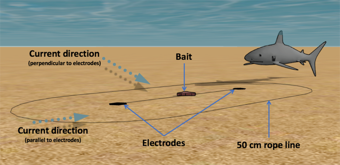
Diagram showing the experimental set-up and the two dominant current directions during the trials. Image drawn by the authors using SketchUp (www.sketchup.com).
Each day, we conducted 12 trials; six with the Scuba7 active and six with the Scuba7 inactive (control). Trials were block randomised so that the status of the Scuba7 (on or off) was randomly selected before each set of two trials. Status of the Scuba7 was confirmed by a green LED light present when turned on. This indicator was not covered during the trials so that the status of the device could be confirmed during the trials. The LED light was not expected to affect sharks as trials occurred during daylight reducing the relative intensity of the LED light, i.e. the intensity of the green light was not strong compared to normal sunlight. During each trial a small piece of local reef fish (bait) was placed between the two electrodes (85 cm from each electrode) using a long pole. Experimenters were not in the water during the trials and stood on a platform ~3 m from the experimental equipment and therefore did not influence shark behaviour. Each trial lasted three minutes or until a shark took the bait. Trial duration was short because of the large number of blacktip reef sharks present and their conditioning to being fed at that location resulting in sharks quickly taking bait. Preliminary tests showed that a bait lasts less than one minute before being consumed by a shark when the Scuba7 is absent. Trials were filmed by a GoPro Hero3+ video camera and footage was viewed using a VLC player. Coding of the video footage was analysed in a single-blind fashion because the coder did not participate in the trials and had no prior knowledge of the status of the Scuba7 when coding videos. Individual sharks could not be identified due to the lack of distinguishable markings or scars and because most sharks were of similar length. Instead, we recorded the maximum number of sharks during each trial within 30 m of the Scuba7. We used the following terminology to describe shark behaviour and code the videos, modified from previous studies12,15:
Approach: a directed swim towards the experimental set-up (each time a shark veered away from the bait and swam back, we classified it as a new approach);
Approach direction: whether sharks approach the Scuba7 from parallel to the dipole axis or perpendicular to the dipole axis;
Distance to electrode: distance from the sharks’ snout, where the shark’s sensory organs targeted by the deterrents (ampullae of Lorenzini) are located, to the closest electrode. Distance was visually estimated to the nearest 10 cm using a rope placed at a known length (50 cm) around the Scuba7 (Fig. 1); and
Reaction: a behavioural reaction from an individual shark towards the experimental set-up (e.g., tail flick, muscle spasm, head shake, fast direction change).
Kevlar-neoprene testing
We tested the Kevlar-neoprene between 0900 and 1200 hours on four days in June 2018. The Kevlar-neoprene consisted of ~1 mm Kevlar knitted sheets (19.5% Kevlar, 70% nylon, 10.5% spandex) glued on both sides of standard neoprene. Sections of Kevlar-neoprene and standard neoprene (without Kevlar) were sawed into 15 × 30 cm pouches on which pieces of meat or local reef fish were attached to entice blacktip reef sharks to bite the neoprene. We also had two neoprene thicknesses for each neoprene type: 5 mm and 3 mm. Neoprene pouches were left in the water until a shark bit the neoprene. Although bite intensity was not recorded, we ensured homogeneity of bites across the material tested by leaving the neoprene until a bite with similar intensity occurred, i.e. head shakes with sharks dragging the pouch in the water, as determined by the senior author (CH). Damages on the neoprene was quantified by a coder who was not present during the trials.
Statistical analysis
Scuba7 testing
We investigated the effect of the Scuba7 on the following response variables: whether the bait was taken, time taken to take the bait, distance to electrode, number of approaches, and whether a reaction was observed. Following the method in Huveneers et al.15, we minimised potential temporal correlation by testing the effects of the Scuba7 on all response variables using a generalised linear mixed-effects model (GLMM) with Day coded as a random effect, the natural logarithm of the maximum number of sharks as offset, and the status of the Scuba7 (on or off) and the approach direction as fixed effects. Current direction was initially included as a fixed factor but was later removed from the model due to strong correlation with approach direction. Dominant current direction was perpendicular to the dipole axis on 4 of the 7 trial days and parallel to the dipole axis on the remaining days, ensuring a relatively balanced current direction across the study period. The error structure of GLMM corrects for non-independence of statistical units due to shared temporal structure and permits the random effects variance explained at different levels of clustering to be decomposed. The inclusion of Day as a random effect enabled the analysis to account for the lack of independence in behaviour within each Day. We determined the most appropriate statistical family and error distribution for each analysis by examining the distribution of the response variable and visually inspecting the residuals for the saturated models. Models were fitted with a gaussian distribution for all parameters tested, except to test the effect of the Scuba7 on the likelihood of the bait being taken for which a binomial distribution with logit link function was used. The number of approaches was scaled and centred prior to fitting the GLMM. The full model was dredged, creating a set of new models containing all possible combinations of the factors. These were ranked on decreasing model fit, using Akaike’s information criterion corrected for small sample size (AICc)36. The bias-corrected relative weight of evidence for each model, given the data and the suite of candidate models considered, was the AICc weight; the smaller the weight, the lower its contribution to parameter estimates36.
Kevlar-neoprene testing
We also used a GLMM to test whether the following response variables were affected by the Kevlar-neoprene: number of punctures (regardless of whether they went through the neoprene or not); whether a puncture went through the neoprene (i.e., hole); and the length of the hole. Day was again coded as a random effect, with the neoprene type and thickness included as fixed effects.
All models were undertaken in R (v.3.5.0) using the lme and glmer function in the nlme and lme4 packages37,38.
Electric field modelling
The effects of undertaking the trials in shallow water was investigated by modelling the electric field propagation across different situations, e.g. in shallow or open water. The electric field was modelled as a dielectric dipole, where each conductive electrode was considered a point load with a charge of q and −q at 1.7 m from each other. Each charge delivers a potential scalar field Vq (Eq. 1):
$${V}_{q}({rm{d}})=frac{q}{4pi {varepsilon }_{0}{varepsilon }_{r}}frac{1}{d}$$
(1)
where ({varepsilon }_{0}) is the permittivity of the empty space; ({varepsilon }_{r}) the relative permittivity of the considered material; and d the distance from the charge q.
The total electric field delivered by the dipole [q, −q] is then calculated by adding the potential scalar field of each electrode, and applying the classic electromagnetism results derived from the Poisson equation (Eqs. 2 and 3):
$$overrightarrow{E}({rm{r}})=-,{rm{grad}},({V}_{tot})$$
(2)
$$overrightarrow{E}={E}_{r}overrightarrow{{U}_{r}}+{E}_{theta }overrightarrow{{U}_{theta }}$$
(3)
$${E}_{r}=K[frac{r-a,cos ,theta }{{({a}^{2}+{r}^{2}-2arcos theta )}^{3/2}}-frac{r+a,cos ,theta }{{({a}^{2}+{r}^{2}+2arcos theta )}^{3/2}}]$$
$${E}_{theta }=K[frac{a,sin ,theta }{{({a}^{2}+{r}^{2}-2arcos theta )}^{3/2}}+frac{a,sin ,theta }{{({a}^{2}+{r}^{2}+2arcos theta )}^{3/2}}]$$
with (K=frac{q}{4pi {varepsilon }_{0}{varepsilon }_{r}})
where ({V}_{tot}) is the total scalar field; r the distance from mid-point between the electrode; (overrightarrow{{U}_{r}}) and (overrightarrow{{U}_{theta }}) the polar projection axes; and (a) the distance between the electrode and mid-point between the electrodes. This provides the electric field delivered by the Scuba7 in open water.
This electric field was then modified to account for the possible effects of the surface and substrate using the method of image charges. This method states that, for a given distribution of charges, the solution of the Poisson equation is unique. Using this principle, we can add some fictive charges to simulate the presence of a non-conductive field (air or seabed) and compare their effect on the electric field. However, this method does not allow us to model the presence of the surface and seabed concurrently. The electric field propagation was therefore modelled for the following situations:
- (1)
Mid-water: Scuba7 away from the surface or the seabed;
- (2)
Surface: Scuba7 was 70 cm from the surface which is considered to be non-conductive. The effect of the seabed was ignored;
- (3)
Bottom non-conductive: Scuba7 was 5 cm from the seabed which is considered to be non-conductive. The effect of the surface was ignored; and
- (4)
Bottom conductive: Scuba7 was 5 cm from the seabed which is considered to be conductive. The effect of the surface was ignored.
Cases (3) and (4) give us information about the effect of the conductive parameter of the seabed.
The selected distances to the surface and seabed replicated the position of the Scuba7 in the trials undertaken whereby water depth was ~75 cm with the electrodes being ~5 cm above the seabed. For each situation, the electric field propagation is represented along the horizontal plane positioned 20 cm above the seabed (Z = −55 cm, which is the average swimming depth of sharks during the trials) and in the vertical plane going through the electrodes.
Using these models, we calculated the field strength that sharks were exposed to when crossing through the dipole axis along three trajectories going through the electrode mid-point: parallel, perpendicular, and diagonally. This allowed us to compare the field strengths that sharks were exposed to accounting for the effects of the surface and substrate as well as the effect of approach direction.
Source: Ecology - nature.com
